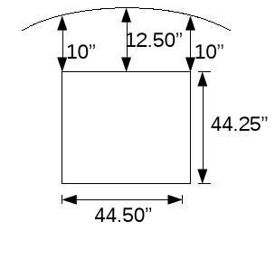
| az,za vs focal plane motions | |||
| moving horn uphill |
same as moving dome uphill | ||
| moving horn ccw (toward stairwell) |
|
||
| plate scales | |||
| x<0 46.79 asecs/inch 18.42 asecs/cm |
x along za
direction positive pointing downhill |
||
| x>0 42.21 asecs/inch 16.62 asecs/cm |
|||
| y 37.08 asecs/inch 14.60 asecs/cm |
y perpendicular to az arm positive pointing toward stairwell |
||
| turret motion | |||
| increasing turret
angle |
moves horn from focus toward the
stairwell (+y direction). same as moving azimuth CCW (to lower angle) |
||
| moving turret 1 deg: =1.276 inches = 3.241 cm =47.3 asecs on sky = 45 asecs on sky (from measurements) |
(1)*!dtor*73.125=1.276 inches 1.276*37.08secs/in=47.3 asecs on sky 45 asecsSky/degTur comes from measurements on sky. |
||
| horn position | |||
| ft |
in |
cm |
|
| 70.48 |
179.02 |
radius for center of horn mount (on the
floor). Assumes feed tower position relative to the 2ndary did not changes after kevlar cable installation (2004). |
|
| 69.41 |
176.30 |
radius for center of horn on floor
(alfa/ao40) germans 1.07" offset |
|
| 8.11 degrees |
horn angle relative to floor perpendicular, tilted so horn is closer to secondary. |
||
| 18.75 |
47.63 |
vertical distance top of floor to horn phase
center. |
|
| 73.151 |
184.34 |
radius center of floor to horn phase center 70.48 + 18.75*tan(8.11) inches |
|
| 70.611 |
179.35 |
scribe mark on rotary floor. |
|
| motion of coma lobe |
moving horn uphill (away from optical axis)
creates coma lobe in - za direction
|
||
| turret floor |
from gregorian upgrade
drawings page s-42. More recent measurements show slightly different values... |
||
| ft |
in |
cm |
|
| 8' 7.75" |
103.75 |
263.53 |
radius of rotary floor |
| 50deg 40deg |
pi sections on the floor they alternate 50deg,40deg |
||
| 4' 6.5" |
54.4 |
138.47 |
diameter 50 deg wedge opening |
| 6' 4.75" |
76.75 |
195.00 |
radius center of 50 deg wedge opening (radiusFloor - 1/2 opening diameter) |
| 3' 6" | 30 | 106.71 | diameter 40 deg wedge opening |
Assumptions:
| Diameter of Hole Opening cm |
Radius on floor @center of
opening cm |
Radius on floor for Focus
mount cm |
Opening Center to floor
Focus mount cm |
useable Diameter cm |
Source of opening diameter |
|
| 138.47 |
188.6 |
std |
179.02 | 9.55 radially in |
119.37 |
upgrade
drawing |
| with -2.72cm offset |
176.30 |
12.27 radially in |
113.93 |
|||
| 142.0 |
186.8 |
std |
179.02 |
7.78 radially in |
126.44 |
ao40
report |
| with -2.72cm offset |
176.30 |
10.5 radially in |
121.0 |

| flrRad cm |
Floor
Radius @ wedge Center cm |
Floor
Radius for focus mount |
alfa
Wedge Center to german's offset focus on floor |
notes |
|
| normal |
with German's 2.72 cm
downhill offset |
||||
| 264.23 | 176.26 |
179.02 | 176.30 |
.04 cm radially out |
assume bottom of wedge centered |
| 264.23 | 177.92 |
179.02 | 176.30 |
1.1 cm radially in |
assume top of wedge centered and 8.17 deg
tilt moves 1.65 cm radially out |
| opening diameter cm |
allowable diameter
using singlePixFocus cm |
allowable diameter
using multiBmFocus cm |
| 138.47 |
119.37 | 113.93 |
| 142.0 |
126.44 | 121.0 |
home_~phil