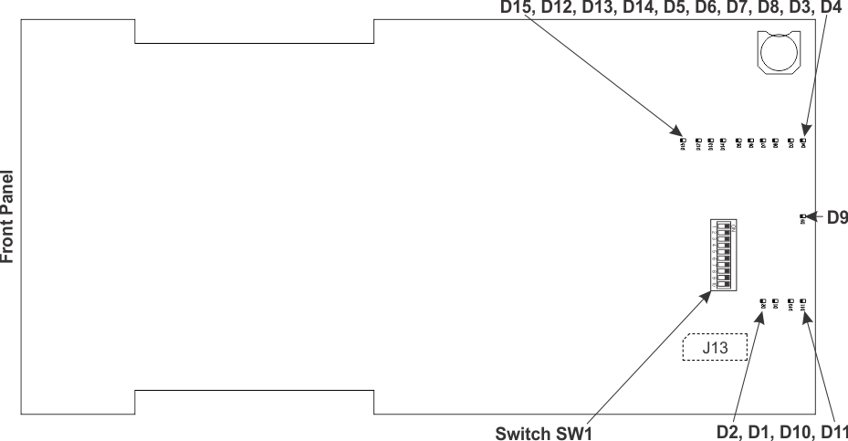
The PCB LEDs, labeled Dnn, are positioned on the solder side of the 71861 main PCB, as shown below
|
LED |
Color |
USE |
|||||
|
D1 |
Green |
Power supply sequencer done |
|||||
|
D2 |
Red |
Power supply sequencer fault detected |
|||||
|
D3 |
Green |
Kintex FPGA initialization complete |
|||||
|
D4 |
Red |
Kintex FPGA initialization in progress |
|||||
|
D5 |
Green |
Kintex PCIe link has been established |
|||||
|
D6 D7 |
Yellow |
Kintex active lanes |
|
x1 |
x2 |
x4 |
x8 |
|
D6 |
Off |
On |
Off |
On |
|||
|
D7 |
Off |
Off |
On |
On |
|||
|
D8 |
Green |
Kintex P16 link has been established |
|||||
|
D9 |
Green |
User−defined LED |
|||||
|
D10 |
Red |
System monitor alarm |
|||||
|
D11 |
Red |
Temperature alarm |
|||||
|
D12 |
Green |
|
|||||
|
D13 |
Green |
|
|||||
|
D14 |
Green |
|
|||||
|
D15 |
Red |
|
|||||