Installing the XMC Module on an XMC Baseboard
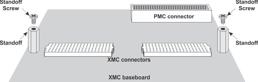
Model 71861 mounts on the connector side of an XMC baseboard or carrier. Refer to the operating manual supplied with your baseboard for any specific mounting instructions. A typical XMC baseboard is shown below

|
Minimum System Requirements: The system in which you install this Pentek product should have the latest Intel® Core™ i7 processor with a minimum RAM of 8 GB. PCIe Gen 3 x8 is required. |
|
|
REMOVE POWER to the XMC baseboard before installation! |

|
|
The Model 71861 requires both a 3.3V and a 5V or 12V power supply (12V is recommended). Ensure that the XMC baseboard or carrier you are using has both a 3.3V and a 5V or 12V power supply. |
Installation Instructions
- Attach an ESD strap to your wrist—attach the other end to a ground source. The ESD strap must be secured both to your wrist and to ground throughout the procedure.
- Pentek XMC baseboards are supplied with module standoffs and mounting screws installed. Ensure that the standoffs on your baseboard are installed at the locations shown in the drawing below and in the Typical XMC Baseboard drawing above.
- Remove the blank module front panel from the front panel of the XMC baseboard (see the Typical XMC Baseboard drawing, above).
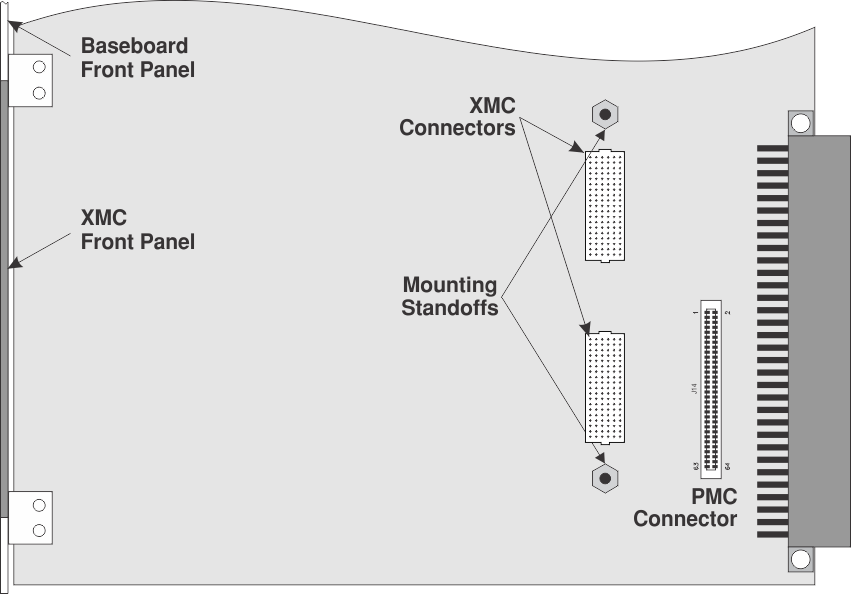
- Position the Model 71861 front panel into the opening from behind the baseboard front panel, and position the module so that the 71861 XMC connectors are over the XMC connectors on the baseboard (see the Baseboard PMC/XMC Connections drawing, below).
- GENTLY but firmly, press down on the 71861 board opposite the connectors to fully seat the board’s connectors into the baseboard. The connectors on the underside of the 71861 PCB should connect smoothly with the corresponding connectors on the baseboard.
- Using two flat−head Phillips standoff screws (supplied with the 71861), secure the Model 71861 PCB, through the PCB’s standoff holes, to the baseboard’s standoffs (see the Baseboard PMC/XMC Connections drawing, above).