The Model 71861 XMC front panel, shown in the drawing on the left, includes six SSMC coaxial connectors for clock, trigger, and analog input signals, and a 26‑pin Sync Bus input/output connector. These connectors are described below.
The front panel also includes ten LED indicators, which are described in Front Panel LEDs.
The front panel has one SSMC coaxial connector, labeled CLK, for input of an external sample clock. The external clock signal must be a sine wave or square wave of +0 dBm to +10 dBm, with a frequency range from 10 to 800 MHz.
This external clock input can be used as the sample clock signal for the A/D converters. The program−selected clock source is input to a CDCM7005 Clock Synthesizer that generates five separate output clocks, each programmable as sub−multiples of the input frequency. One of the CDCM7005 output clocks (Y0) provides the sample clock for the ADS5485 A/D converters.
When greater than 200 MHz, the input clock must be divided down by the CDCM7005 for the ADC sample clock.
|
|
Take care that the ADC clock output from the CDCM7005 never exceeds the ADS5485’s rated clock speed during any change of frequency with the VCXO and/or the CDCM7005.
− If you are increasing the VCXO frequency, first adjust the appropriate CDC divider so that the ADS5485 clock does not exceed 200 MHz.
− If you are decreasing the VCXO frequency, do not adjust the CDC divider until the VCXO has been reprogrammed so that the ADS5485 clock does not exceed 200 MHz. |
The front panel has one SSMC coaxial connector, labeled TRIG, for input of an external trigger. The external trigger signal must be an LVTTL signal.

|
The front panel TRIG input is 5V tolerant but it must NOT have any negative voltage applied. It is terminated with a 392−ohm resistor to 3.3V and a 332−ohm resistor to ground. |
The trigger input can be used as a gate or trigger for A/D signal processing.
Analog Signal Input Connectors
The front panel has four SSMC coaxial connectors for analog signal inputs, labeled IN 1, IN 2, IN 3, and IN 4, one for each ADS5485 A/D converter.
Each analog input signal has a full−scale level of +8 dBm. Each input drives an RF transformer with 50−ohm input impedance.
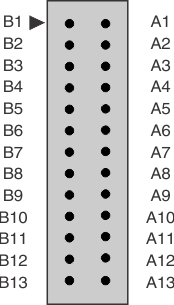
The 26−pin Sync Bus front panel connector, labeled SYNC/GATE, provides clock, sync, and gate input/output pins for the Low−Voltage Positive Emitter−Coupled Logic (LVPECL) Sync Bus. When Model 71861 is a bus Master, these pins output LVPECL Sync Bus signals to other slave units. When Model 71861 is a bus Slave, these pins input LVPECL signals from a bus Master. This connector also accepts two Low−Voltage TTL (LVTTL) Gate/Sync inputs.
The table below shows the SYNC/GATE connector pin configuration. The mating 26−pin connector is Pentek part # 353.02607 (Model 2140−998).
|
Signal |
Pin |
|
Pin |
Signal |
|
LVTTL GATE/TRIG |
B1 |
A1 |
GND |
|
|
LVTTL SYNC/PPS |
B2 |
A2 |
GND |
|
|
LVPECL GATE− |
B3 |
A3 |
LVPECL GATE+ |
|
|
GND |
B4 |
A4 |
GND |
|
|
LVPECL SYNC− |
B5 |
A5 |
LVPECL SYNC+ |
|
|
GND |
B6 |
A6 |
GND |
|
|
LVPECL CLK− |
B7 |
A7 |
LVPECL CLK+ |
|
|
GND |
B8 |
A8 |
GND |
|
|
Spare |
B9 |
A9 |
Spare |
|
|
GND |
B10 |
A10 |
GND |
|
|
Spare |
B11 |
A11 |
Spare |
|
|
GND |
B12 |
A12 |
GND |
|
|
Spare |
B13 |
A13 |
Spare |
|

|
When connecting LVPECL Sync Bus pins to additional Model 71861 modules, the LVPECL pins on the LAST unit must be terminated. Pentek includes a terminating board (part # 004.71504, Model # 2140−999) with your shipment for this purpose. |

|
The LVTTL GATE/TRIG and SYNC/PPS signals are 5V tolerant but they must NOT have any negative voltage applied. They are terminated with a 392−ohm resistor to 3.3V and a 332−ohm resistor to ground. |


