| dipole | linefeed | |
| Tsys(za=15) | 167 | 100 |
| gain(za=15) | .6 K/Jy | 10.5 K/Jy |
| sefd(za=15) 3C48 | 270 Jy | 9 Jy |
| beam width | 18 Amin | 9.5 Amin |
| az pnt err (avg)
zapnt err (avg) |
1.0 amin
-.7 amin |
-.25 Amin
-.1 Amin |
| az pnt offset used:
ch pnt offset used |
0.4833 deg
-1.5483 |
|
| az pnt offset measured
za pnt offset measured |
0.467 deg
-1.540 |
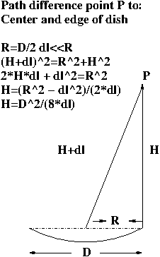
The near/far field transition occurs when the path difference for a ray from the center of the dish and the edge of the dish to a point P have a phase difference that is some fraction of lambda. The picture below shows the path difference dl vs the H and the illuminated Radius:

Using the hpbw to define the illuminated area (d=k*lambda/hpbw) and solving for H gives:
| lineFd | Yagi | |
| HPBW (far field) | 9.5 amin | 18 amin |
| Illuminated Diam=1.2*.7/(hpbw) | 304 meters | 160 meter |
| Near/farField Transition: D^2/lambda | 132 km | 37 km |
Meteors occur around 100km. At this height,
the linefeed
is still in the near field while the yagi is in the far
field. The
angles and distances of the two beams at 100 km are shown below
(assuming
the far field..).
|
|
|
|
| pnt Offset relative to Lf
(farfield) |
0 | 1.622 deg |
| Offset len @100km | 0 | 2.83 km |
| angle , distance | angle,distance | |
| 1st sdLb: angle,dist@100km | 14.25', .41 km | 27', .78 km |
| 2nd sdLb:angle,dist@100km | 23.75', .69 km | 45', 1.3 km |
| 3rd sdlb: angle,dist@100km | 33.25', .97 km | 63', 1.83 km |
| 4th sdlb: angle,dist@100km | 42.75', 1.25 km | 81',2.36 km. |
| 5th sdlb: angle,dist@100km | 52.25', 1.52 km | 99',2.88 km. |
The yagi sidelobes move by about .53 km per sidelobe at 100 km. The lf sidelobes move by .28 km/sdlb at 100 km (if they were in the far field). The offset direction of the yagi relative to the linefeed is determined by the az,za pointing offsets.
| lf sidelb/dist | yagi sidelb,dist | total
distance |
strength
rel to lf mainbm |
strength
rel to max |
| 0,0 | 5,1.52 | 2.88 | 3.36e-3 | 1 |
| 1,.41 | 4,1.25 | 2.77 | 2.37e-3 | .071 |
| 3,.97 | 3,.97 | 2.8 | 6.95e-5 | .021 |
| 5,1.52 | 2,.69 | 2.82 | 5.5e-5 | .016 |
home_~phil